

Sign up for our Newsletter
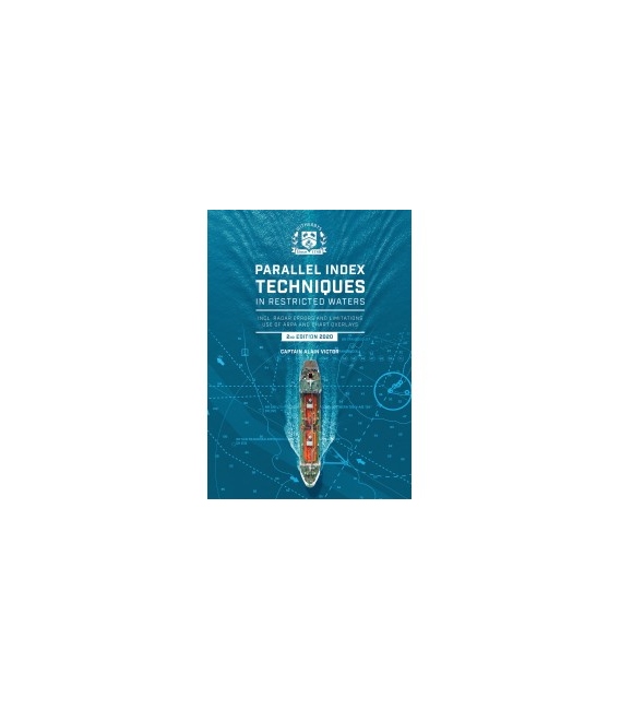
Parallel Index Techniques in Restricted Waters, 2nd Edition 2020
Title: Parallel Index Techniques in Restricted Waters. Incl. RADAR Errors and Limitations. Use of ARPA and Chart Overlays (2nd Edition)
Subtitle: Incl. RADAR Errors and Limitations. Use of ARPA and Chart Overlays (2nd Edition 2020)
Product Code: IT102979
Published Date: August 2020
Binding Format: Paperback
Book Height: 275 mm
Book Width: 215 mm
Book Spine: 5 mm
Weight: 0.90 kg
Author: Alain Victor
Parallel Index Techniques in Restricted Waters. Incl. RADAR Errors and Limitations. Use of ARPA and Chart Overlays, 2nd Edition 2020
Parallel indexing is a well established method of constantly monitoring a vessel’s position.
In marine navigation, the main goal of radar is to detect any vessels in the vicinity of the ship or any obstacles, such as land masses, in reduced visibility. Radar is also widely used in good visibility.
Technological improvements and development refinements have allowed users to stretch the use of radar to its limits.
The purpose of this book is to explain how it can be done safely.
Foreword
Preface
1 Introduction
2 Relative Stabilised Presentation, Quick Review
2.1 Characteristics
2.2 Advantages when using parallel index technique
2.3 Disadvantages
3 Relative Unstabilised Display
4 True Motion
5 Word of Caution
6 Principles of the Parallel Index Technique
7 Relation Between ROT, SMG and Radius of Turn
7.1 Worked Example
7.2 How to Quickly Find the Centre of a Turning Circle?
8 Beam Width Distortion and Effect on Parallel Index Technique
8.1 3 cm RADAR Beam Widths (Approximate and Calculated)
8.2 Calculated Beam Widths for 10 cm RADAR
9 Range Scale 3 Miles, Beam Width Effect Alone
10 Important Remarks
11 Measuring Beam Width
12 Measuring Beam Width without Buoys or Information in a Ship’s Manual
13 Improper use of PI Technique
14 Practical Examples of being in a Channel
15 Example with Land Target Abaft the Beam
16 Effect of Echo Enhancing
17 The “Total” Method
18 Range Error or RE
19 Ship Alongside
20 Detecting RE without Quantifying it
20.1 Under Ranging
20.2 Over Ranging
20.3 Blind Circle
21 Collateral Effect of RE on PI Technique
22 Adjusting and Using PI Technique when RE is Known
23 Heading Marker Alignment
24 Practical Example of HM Misalignment
25 Gyro Error and Effect on Parallel Index Technique
26 Practical Example
27 Error Analysis in Reduced Visibility
28 When not to use Parallel Index Technique
28.1 Final Orientation
28.2 Gyro Lag
28.3 Gyro Drift
28.4 Substantial RE
29 Analogue Radars (CRT)
29.1 Non-Linearity
29.2 Velocity Error
29.3 Ovoid Rings
30 Radar Repeater
31 Radar Check (Example)
32 COG Vector Derived from GPS Displayed on Radar
33 Extremely Important
34 AIS and Anti-Collision
35 Some Myths
35.1 Port Side of a Target
35.2 Measuring RE
35.3 Measuring RE with PI Lines
35.4 Effect of Beam Width Alone if not Accounted for
35.5 Effect of Beam width Properly Accounted for
35.6 Heading Marker Slewed 2° to Port
35.7 One Side Only
36 Conclusion
37 References
Appendix 1 ECDIS and Radar Answers
Appendix 2 AIS Position Discrepancies
Appendix 3

