

Sign up for our Newsletter
")
")

Pub. No. 229 Vol. 6: Sight Reduction Tables For Marine Navigation Latitudes 75°–90°, Inclusive
Many requirements exist for the solution of the general astronomical or navigational triangle, for which the navigator’s needs are foremost; for upon its accurate and rapid solution depends his effectiveness in locating himself expeditiously upon the Sumner Line of Position. This six-volume series of Sight Reduction Tables for Marine Navigation is designed to effect all solutions of the navigational triangle, having given two sides and the included angle, to find a third side and adjacent angle. A simple method is suggested for extracting from the tables the numerical value of the parallactic or position angle, thus completing the triangle solution by providing the sixth element. The tabular data are arranged to facilitate rapid position-determination utilizing the Marcq Saint Hilaire or intercept method.
Tabulations for entering arguments of integral degrees of latitude, declination, and local hour angle include computed values of altitude, successive altitude differences with sign, and azimuth angle. The data are applicable to the solution of sights of all celestial bodies, for latitude and declination of both same and contrary name. Altitudes and their differences are tabulated to the nearest tenth of a minute, azimuth angles to the nearest tenth of a degree. The tables, intended for use with The Nautical Almanac, are designed for precise interpolation of altitude for declination only, utilizing convenient interpolation tables which facilitate linear interpolation and provide additionally for the effect of second differences when required. Interpolation of altitude for latitude and local hour angle may also be made by employing the diagrams provided.
The primary table entry is local hour angle¾not meridian angle¾which is measured westward through 360° from the local meridian to the hour circle of the body. Each volume covers 16° of latitude and is arranged in two zones of 8° each. All latitudes of a zone appear as horizontal entries above each column on every page of that section of the volume, the first degree of each volume overlapping the last degree of the preceding volume. All declinations are given as vertical arguments on each page. Altitudes are tabulated from the horizon to the zenith. Azimuth angles are tabulated through 180°, and rules appear on each opening of the tables for converting azimuth angle to true azimuth. Full explanation of the tables’ concept, format, arrangement, and method of interpolation is given in the Introduction. Included examples illustrate methods and techniques employed. Peculiarities of the tables and their application to the solution of certain navigational problems are also covered. Standard navigational manuals should be consulted when more detailed information on line of position methods and techniques is desired.
These new tables, although similar to H.O. Pub. No. 214 (H.D. 486 in the United Kingdom), Tables of Computed Altitude and Azimuth, provide full coverage, and are compact in design, format and arrangement. Their completeness and utility suggest their possible broad application to the solution of many space-age problems in closely associated fields of science and technology. For air navigation the H.O. Pub. No. 249 (A.P. 3270 in the United Kingdom) series of tables, consisting of three volumes and entitled Sight Reduction Tables for Air Navigation, is recommended.
The concept, design, development, and preparation of these tables are the results of the collaborative efforts and joint accomplishments of the U.S. Naval Oceanographic Office, the U.S. Naval Observatory, and Her Majesty’s Nautical Almanac Office, Royal Greenwich Observatory. The tables in identical format are being published by the British Ministry of Defence as a Hydrographic Department publication.
| PREFACE | III | |
| EXPLANATORY NOTE | V | |
| TERMINOLOGY. | VI | |
| INTRODUCTION | ||
| A. DESCRIPTION OF TABLES | ||
| 1. Purpose and Scope | VII | |
| 2. Arrangement | VII | |
| B. NORMAL USAGE | ||
| 1. The Intercept Method | IX | |
| 2. Entering Arguments | IX | |
| 3. nstructions for Usen | IX | |
| 4. Illustrations of Use | X | |
| C. ALTITUDE INTERPOLATION, SPECIAL TECHNIQUES | ||
| 1. Interpolation when Second Differences are Required | XIII | |
| 2. Interpolation near the Horizon | XIV | |
| 3. Negative Altitudes | XV | |
| 4. Interpolation near the Zenith. | XV | |
| 5. Indeterminate Azimuths | XVII | |
| 6. Interpolation for Latitude and Local Hour Angle | XVII | |
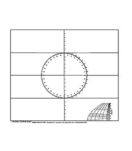
| 7. Position Circles and Position Lines. | XXI | |
| 8. Construction of a Plotting Sheet | XXIII | |
| 9. Variation of Altitude with Time | XXIII | |
| 10. Polar Plotting | XXIII | |
| 11. The Polar Grid | XXVI | |
| D. OTHER APPLICATIONS | ||
| 1. Star Identification | XXVI | |
| 2. Great-Circle Sailing | XXVIII | |
| 3. Composite Sailing | XXX | |
| 4. General Spherical Triangle Solution | XXXI | |
| E. BACKGROUND | ||
| 1. Accuracy of Tables | XXXII | |
| 2. Production and Printing | XXXII | |
| SIGHT REDUCTION TABLES | ||
| Latitudes 75° to 82° | 2-183 | |
| Latitudes 83° to 90° | 184-365 | |
| INTERPOLATION TABLE | ||
| Declination Increment—0.0' to 31.9' | Inside front cover | |
| Declination Increment—28.0' to 59.9' | Inside back cover | |
| DIAGRAMS A, B | Between 183-184 | |
| C | Loose insert | |